Computational Fluid Dynamics (CFD)
Computational Fluid Dynamics (CFD)
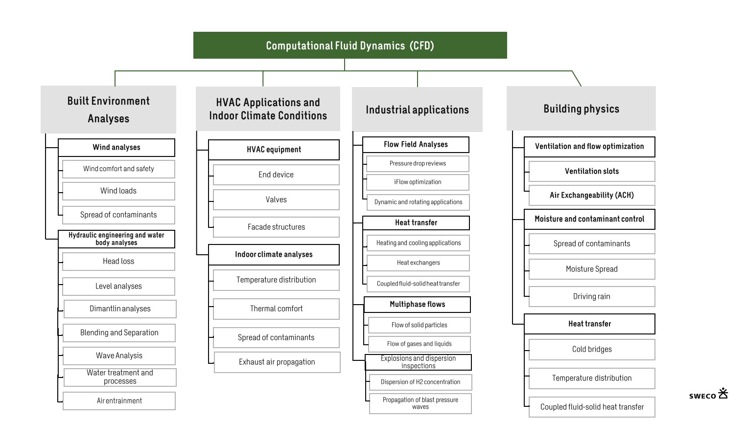
Computational Fluid Dynamics (CFD) is a well-established and commonly used mathematical method for simulating flow phenomena for gases and liquids in various of applications.
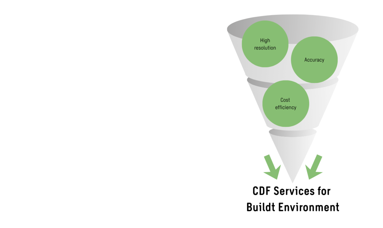
We use modern tools and high-performance computing environments in our simulations to provide fast delivery and both high accuracy and high resolution. CFD enables virtual prototyping early in the design process providing valuable insight and detailed information which enables reaching sustainable goals more efficiently, faster design process as well as significant potential for economical savings.
Fluid dynamics calculation methods
- Pre-processing – Generation of 3D geometry and the computational mesh
- Numerical solution – Numerical solution of the flow-governing Navier–Stokes equations, either in a steady-state or time-dependent form
- Post-processing – Processing numerical simulation data into visualizations and animations
Computational fluid dynamics services
We offer a wide range of CFD simulation services for various applications. You can find more examples of our CFD services behind the links:
- General CFD Services : Sweco CFD Services
- Data Center CFD Services: CFD Services for Data Centers
- Explosion and Blast Wave Analysis: Explosion and Blast Wave Analysis
- Water Engineering: Sweco CFD Services in Water Engineering
CFD simulations are typically used in the following applications:
Indoor Environment Analysis
- Temperature distribution and thermal comfort (draught risk) in complex and large indoor environments
- Operation and efficiency of HVAC systems and components
- Air handling and mixing of air
- Contaminant dispersion and control
Wind Engineering
- Wind comfort
- Wind loads
- Air pollution dispersion
Water Engineering
- Flow analysis of water bodies, rivers and dams
- Flow analysis of powerplants and spillways
- Flow analysis of harbors and canals
Industrial applications
- Pressure loss and flow patterns
- Multiphase flows
- Heat transfer
- Process simulations
- Rotating machines
- Particle simulations
Building physical simulations
- Ventilation of structures
- Moisture and heat transfer
Virtual wind tunnel utilizes
Virtual wind tunnel utilizes
Virtual wind tunnel utilizes:
- The 3D built environment model
- The 3D terrain model
- Statistical measurement data for the local wind
CFD simulations for built environment enables to
- Design and increase outdoor comfort in urban environments
- Study the dispersion of pollutants in air due to wind
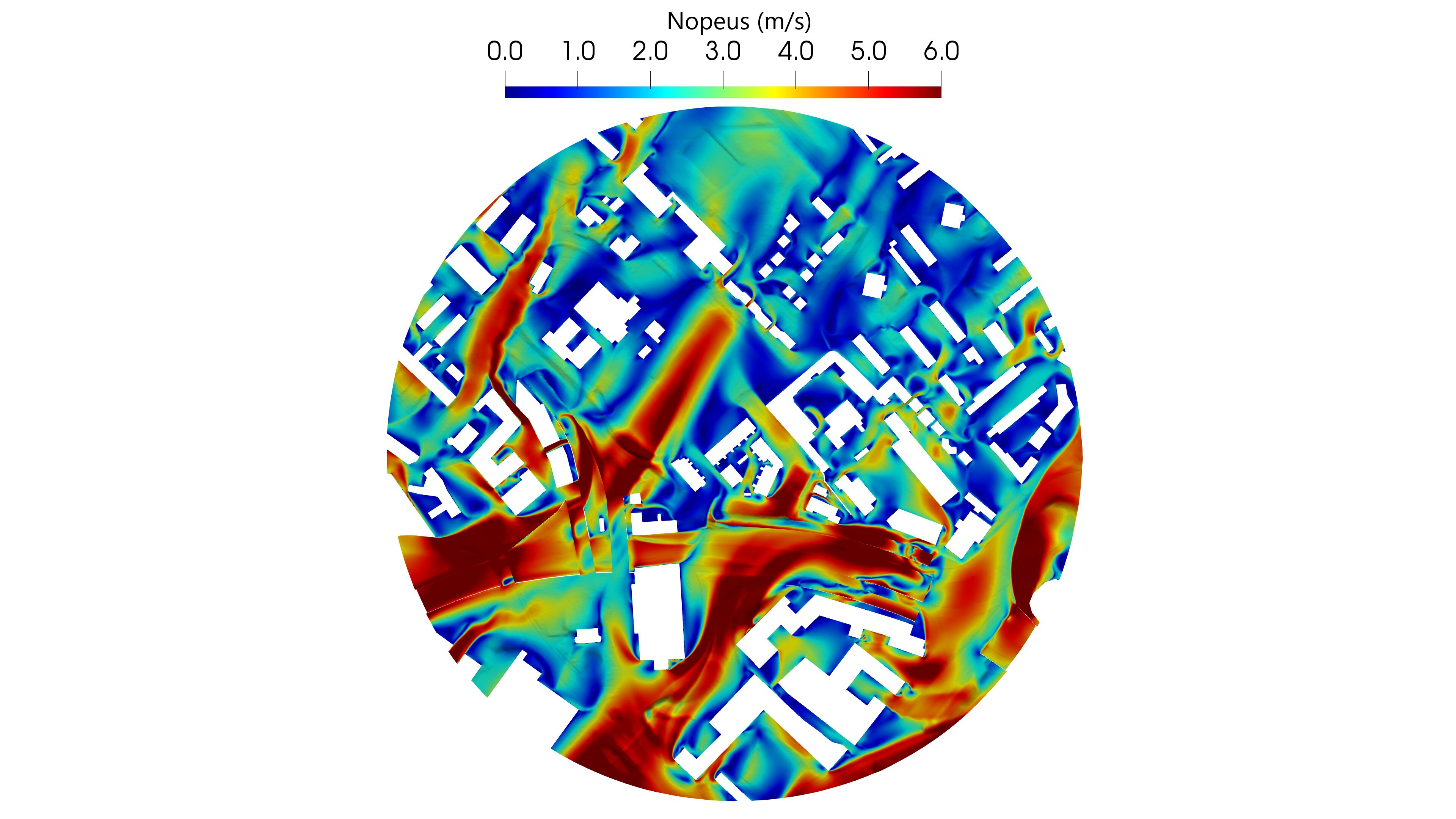
Wind tunnel is a tool to analyse the effects of air moving past solid objects such as buildings.
A wind tunnel consists of the objects mounted on a tubular passage where air is made to move part the objects.
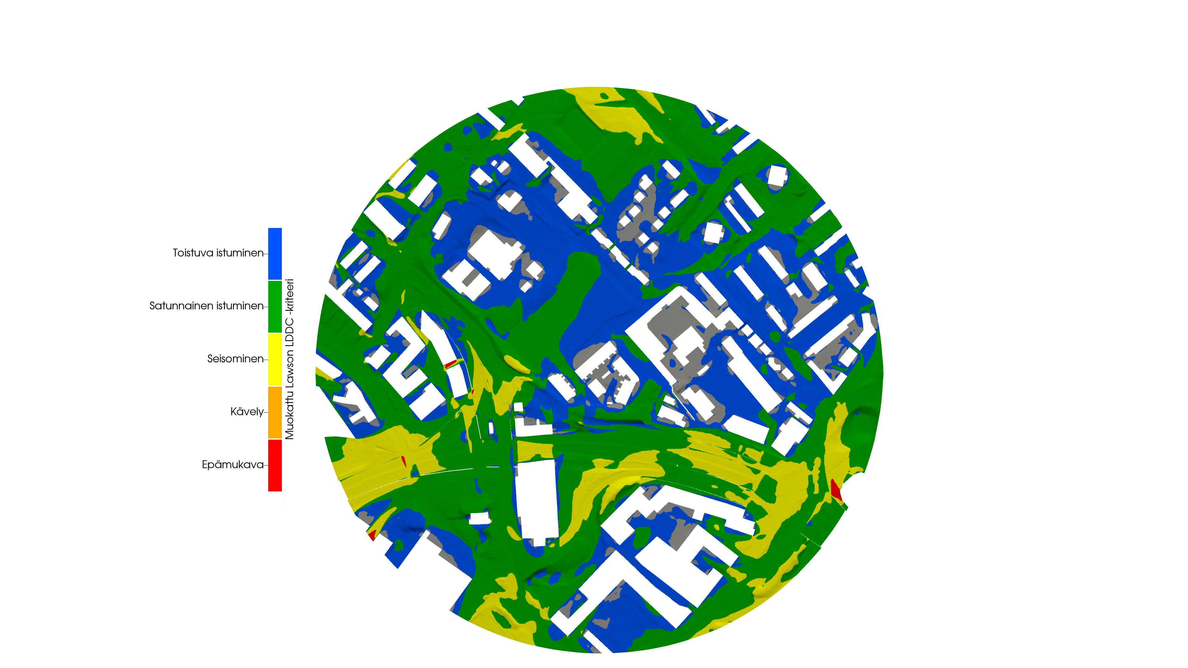
Wind Comfort
A wind comfort assessment analyzes the effects of wind on the comfort of users in the built environment. Based on the results, the built environment is classified by area according to its suitability for different user activities, such as sitting (terraces, parks, etc.), standing (entrances, bus stops, etc.), or walking (pedestrian routes). The assessment helps identify potential shortcomings related to wind comfort and safety and allows the effectiveness of mitigation measures to be verified already at the design stage, enabling a cost-efficient design process.
Industrial applications and systems of flow simulation
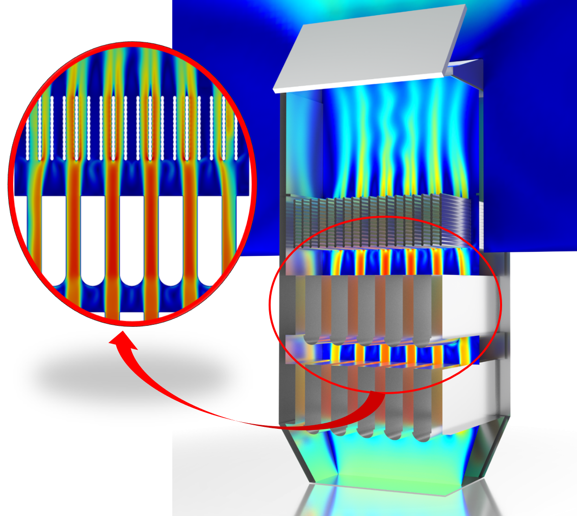
By optimizing the flow field, application performance and functionality can be improved while achieving cost savings. Computational fluid dynamics (CFD) makes this possible already at the design stage, without the need for a single physical prototype. Even small details can be significant from a flow perspective; for example, relatively minor changes to geometric shapes can result in substantial performance improvements. The operation of many applications is based on exploiting flow phenomena in detail. For instance, flow separation from a surface or flow restriction are key mechanisms underlying the performance of, among others, heat exchangers and air terminal devices.
The total cost of an application includes various design and product development expenses. Virtual prototyping makes it possible to reduce many of these costs and bring a more functional product to market. Reduced prototype manufacturing and increased understanding of the application’s flow phenomena are also typical benefits of flow simulation.
Flow optimization
Multiphase flows
Heat storage systems
Dynamic applications
Industrial components
Heat transmission
Particle simulations
Analyses of water bodies, dams, and harbors
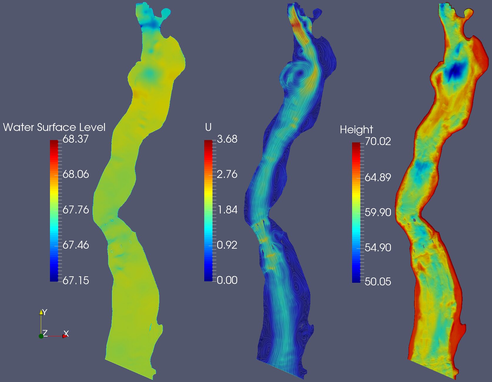
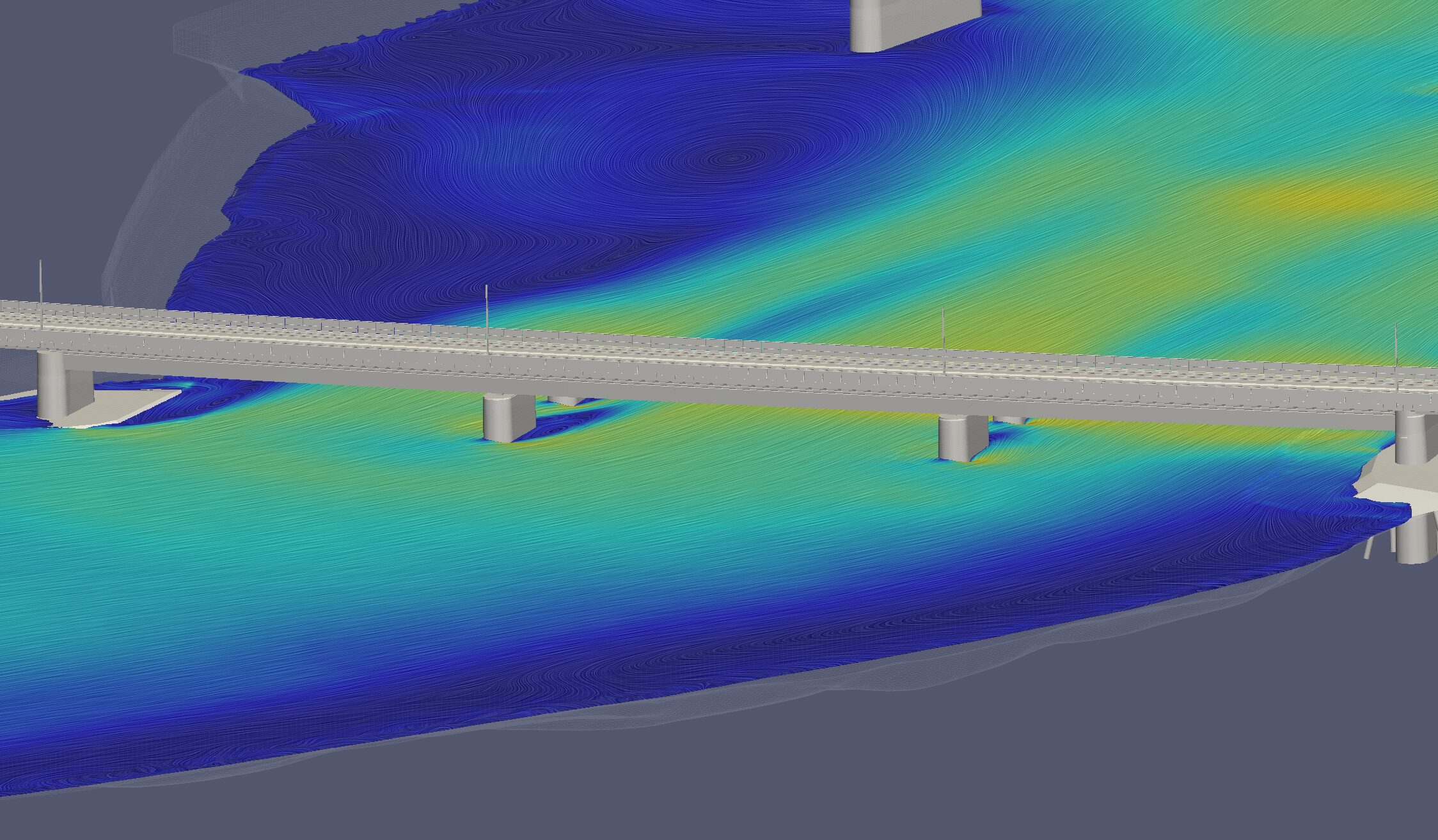
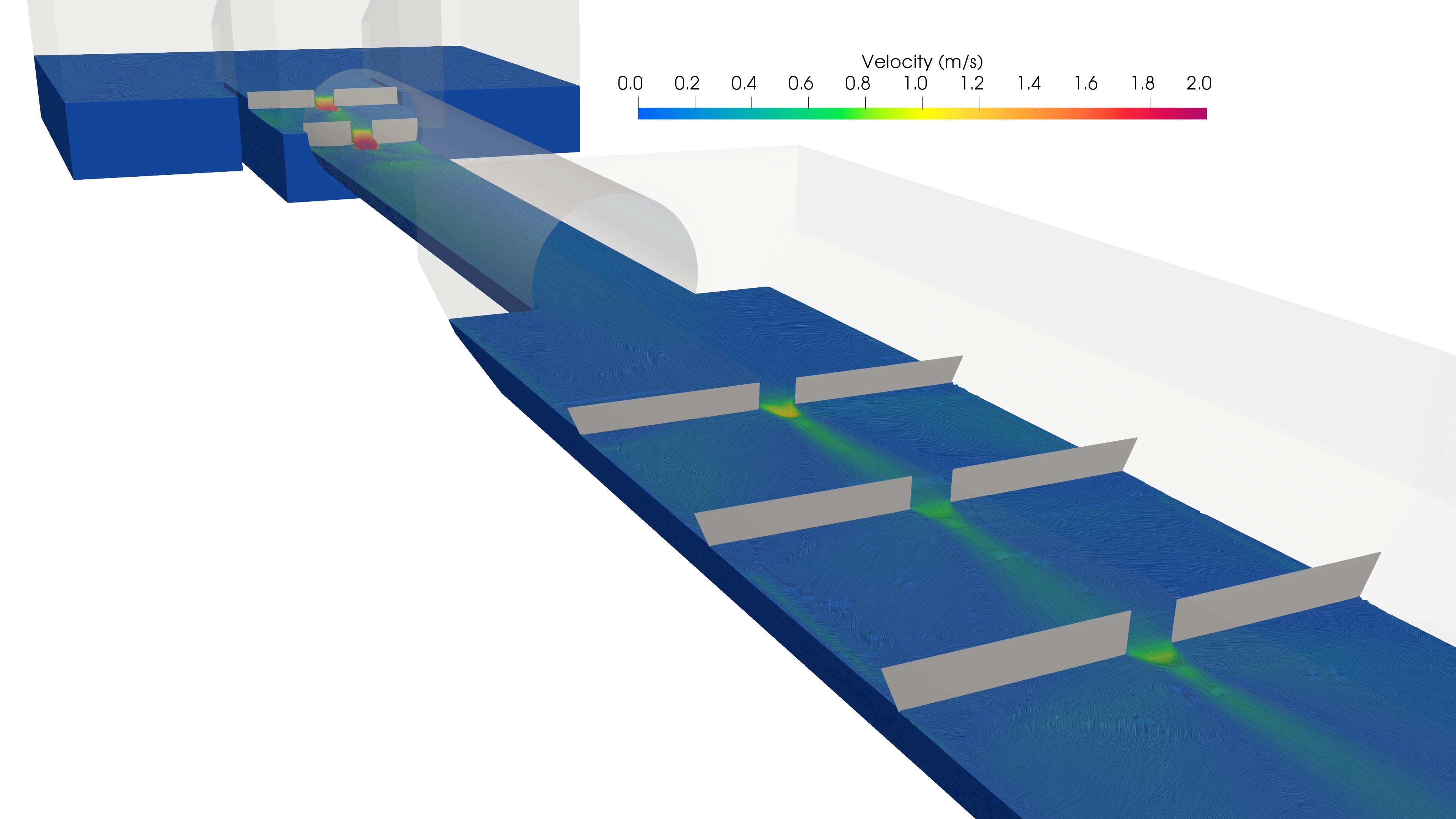
Water flow is often a recurring type of multiphase flow (water + air). In the case of dams, for example, the moving water masses are often large, making their control critically important. Flow-related challenges may include aspects related to energy production, the management of various overflow situations, rising water levels, flooding, or preparedness for loads imposed on structures. Moving water masses are often associated with time-dependent fluctuations, which can be taken into account using computational fluid dynamics (CFD). Similarly to wind loads, flowing water generates pressure loads on solid structures, which can be accurately resolved through flow simulations.
Air entraiment
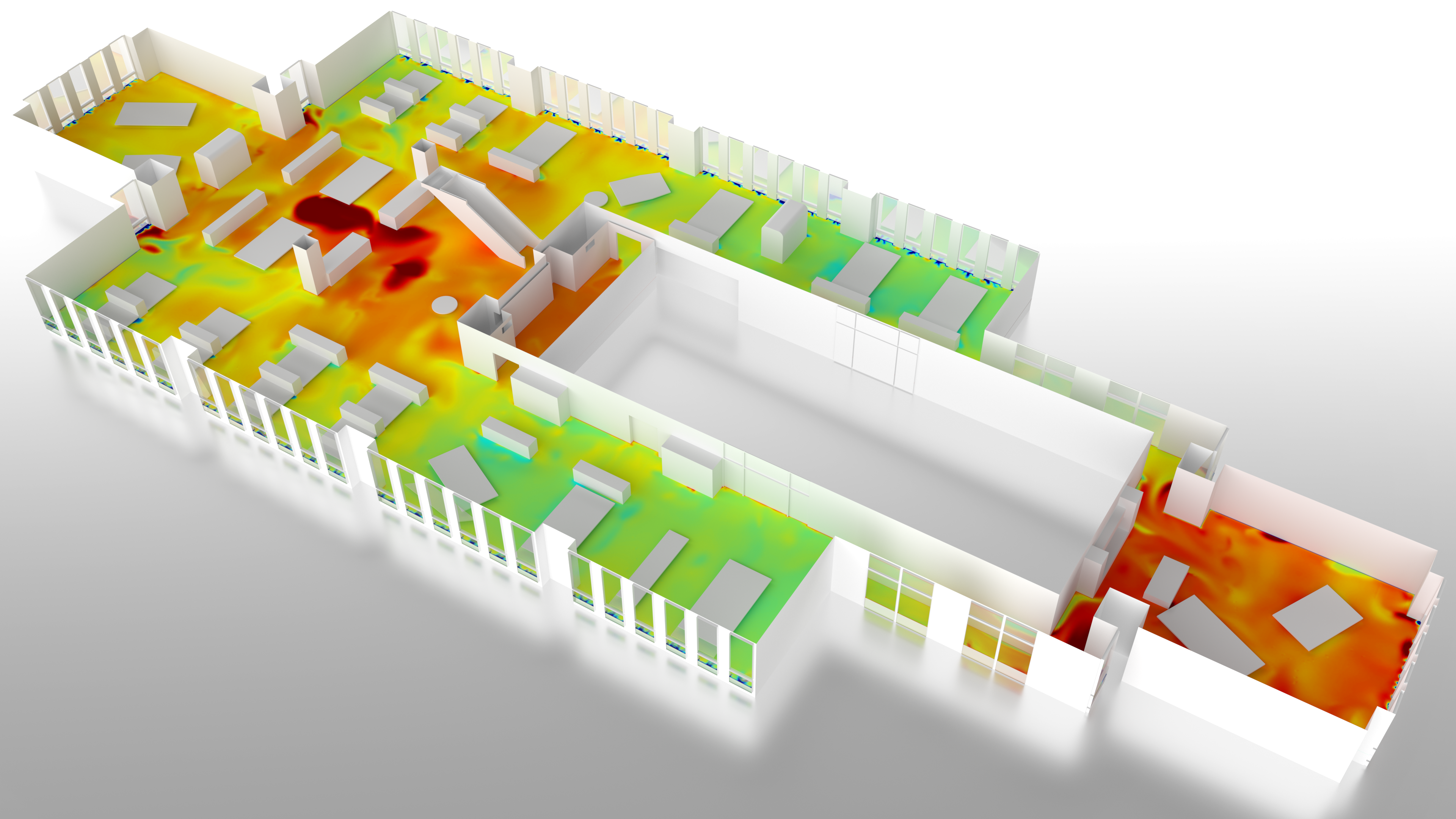
Indoor climate design and validation
People spend over 90% of their time indoors. Indoor environmental quality links the overall health of buildings with the safety, comfort, and well-being of occupants, as well as employee productivity. Poor indoor environmental quality can lead to dissatisfaction and health risks for both users and the building itself.
A safe, comfortable, and energy-efficient indoor environment can be achieved through good design. Heating and cooling large or complex spaces is a challenging engineering task, especially during the warmest and coldest periods of the year. A common question is whether the designed ventilation and cooling solution provides a comfortable indoor environment even under peak thermal loads. Modern architectural solutions further challenge the design of high-quality indoor climates.
Heat distribution
Indoor environmental conditions are often designed to be as uniform as possible using mixing ventilation. The aim is to create a comfortable and safe environment for occupants regardless of their location within the space. Providing clean, fresh indoor air and a uniform temperature distribution in large or complex spaces requires expertise and advanced tools.
Heat comfort
Thermal/heat comfort describes occupants’ satisfaction with the thermal conditions of the indoor environment. It is not determined solely by indoor air temperature, but is a combination of several factors. For example, air movement can cause a sensation of draft and plays an important role especially when cooling indoor spaces or near large windows during the winter months. Draft risk describes the relative proportion of people dissatisfied with the indoor environment as a function of air velocity, turbulence intensity, and air temperature. By using computational fluid dynamics (CFD), higher-quality indoor environments can be created by minimizing the draft risk experienced by occupants
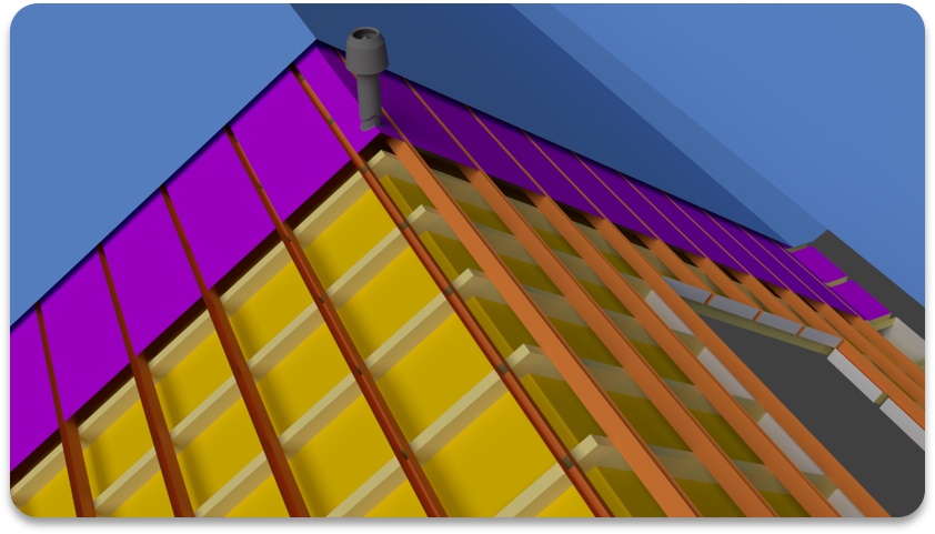
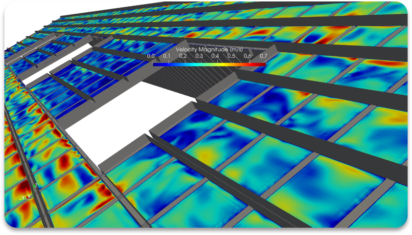
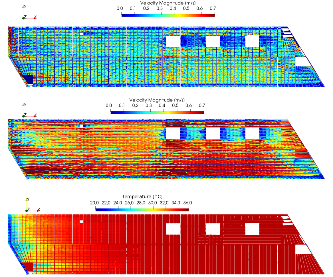
Building Physics
The detailed design or validation of the performance of different structures enables the assessment of ventilation efficiency, moisture behavior, and heat transfer even in complex structural systems.
Eero Kokkonen
Department Manager, Chief CFD Engineer